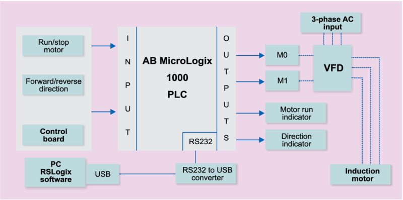
A motor is connected to plc. For single phase motor reversing start lead with respect to the main leads.
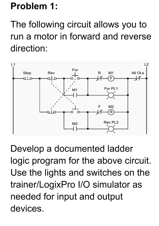
Forwardreverse ladder circuits.
You can find out more Diagram below
Plc ladder diagram forward reverse. Demikianlah artikel singkat tentang ladder diagram plc untuk motor forward reverse pada automatic sliding door. And for dc motor reversing the field. Artikel ini bukanlah tutorial hanya untuk pengayaan ilmu saja bagi pembaca.
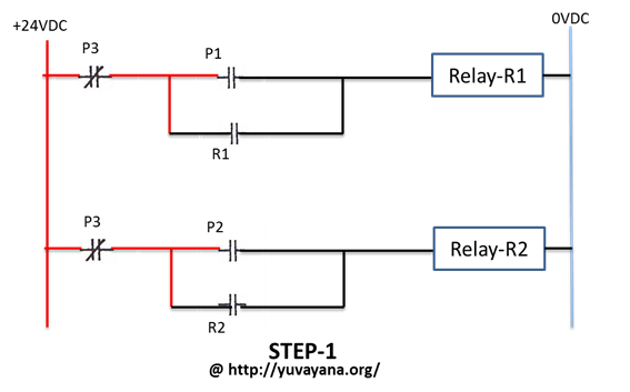
We can also design this logic with relay circuit. In this application we will use siemens s7 1200 plc and tia portal software for programming. The plc implementation of the circuit includes all of the elements in the hardwired diagram even though the additional starter contacts are not required since the push button interlocking accomplishes the same task.
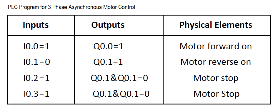
3 phase motor control using plc ladder logic s bharadwaj reddy may 18 2018 april 11 2019 3 phase motor control using plc this is plc program for forward and reverse control for 3 phase asynchronous motor. This blog post is not only intended to provide a graphical illustration but will also explain the procedure and the operational concept involving the wiring principle of the forward reverse motor control circuit with the use of a plc programmable logic controller. The ladder circuit that latches the overload condition forward or reverse must be programmed before the circuits that drive the forward and reverse starters as we will explain shortly.
Watch now 46 5531 more less. Learners examine the method of interpreting the truth tables for two position and three position selector switches on ladder logic circuit diagrams. Otherwise the plc program will never recognize the overload signal because the starter will be turned off in the circuit during the same scan when the overload occurs.
A diagram of the ladder program contained inside the plc memory specifically. Determining the complex conjugate. For any three phase ac motor reversing can be accomplished by reversing any two leads.
This circuit is also known as forwardreverse control for 3 phase induction motor. Plc ladder diagram for forwardreverse control of motor. Saran masukan ataupun koreksi silahkan meninggalkan jejak di kolom komentar.
However after the overload condition passes the operator must push the reverse or forward push button again to restart the motor. Run this motor in the forward and reverse direction using ladder diagram programming language.


0 comments:
Post a Comment