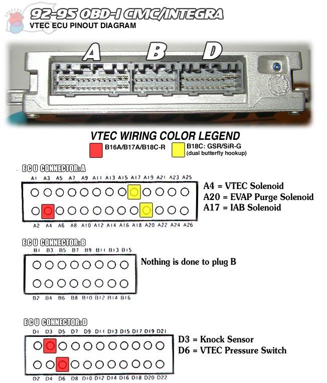
The appropriate engine wiring diagram can be used along with these ecu connector pinouts. Is 1994 integra ecu obd1.
Picture shows aem ecu socket.
You can find out more Diagram below
Integra obd1 ecu pinout. A c and d. Yes the gsr wiring will work. A b and c.
Obd1 plug configuration below is an example that shows the common onboard male connectors for a honda obd1 ecu. Pinouts for honda obd1 ecus such as those fitted to 1992 1995 honda integra 1992 1995 honda civic inc delsol 1992 1995 honda prelude as well as others. Or will i have to but any parts.
Obd0 pm6 si ecu pinout 88 91 civic si. Take note of plugs. I have 2 complete cars engine wiring ecu interior etc.
Just in the ecu engine control unit programming. Crx si 90 91 integra. You would need a conversion harness for 90 91 integra or 96 later integra.
3 plug and 4 plug ecus use the same pins. Obd2a plug configuration below is an example that shows the onboard female connector configuration for an obd2a ecu. Take note of plugs.
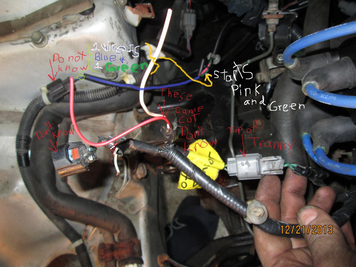
The 4 plug obd1 connector image below is proof these do exist and are usually found on jdm auto 92 95 civic integra and preludes. Also your ecu will work for any obd1 92 95 integra chassis check years that was just a quick google search. Asked in car fuses and wiring acura integra windshields and wipers 1995 1999 dodge plymouth neons.
Obd2b plug configuration below is an example that shows the onboard female connector configuration for an obd2b ecu. The blank connector d is only used with at specific civicintegra vehicles. The blank connector b is only used with civicintegra vehicles equipped with at.
A b and d. Obd1 ecu pinout civic 92 95 integra. The only difference between gsr and lsgs wiring is vtec.
Take note of plugs. Yo hkblur thatnks for the info but i have a question if i were to just move all wiring from the db8 obd2 gsr and put it in the db7 obd1 ls would i need to do anything esle to make sure it functions correctly.


0 comments:
Post a Comment