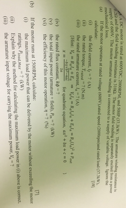
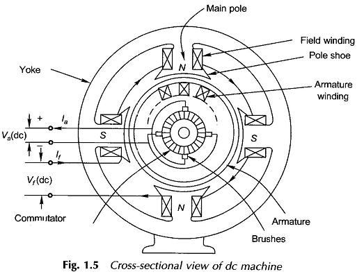
Armature winding of a dc machine basically armature winding of a dc machine is wound by one of the two methods lap winding or wave winding. Armature winding armature windin g is the windings in which voltage is inducedthe field winding is the winding in which the main field flux is produced when the current through the winding is passed.
Series wound motors have the armature connected in series with the field.
You can find out more Diagram below
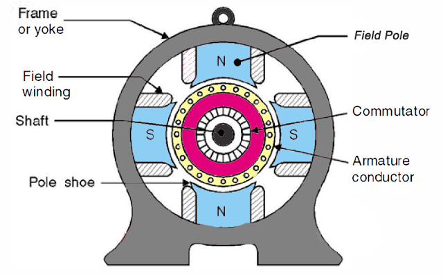
Armature and field winding of dc motor. In this type the field is in series with the armature. The armature interacts with the magnetic field in the air gap. Also many newer motors are designed to be brushless.
Field winding in dc machines is to produce poles around armature winding. The motor design is referenced by the method these two components are wired together. Field windings on static core and in the form of simple winding to produce magnetism in poles of different pole placed diametrically opposite.
In addition many motors are using permanent magnet fields. This type of motor is only used for direct coupling and other work where the load is permanently coupled to the motor. The field component can comprise either permanent magnets or electroma.
The difference between these two is merely due to the end connections and commutator connections of the conductor. The armature can be on either the rotor or the stator depending on the type of electric machine. As you already know there are two electrical elements of a dc motor the field windings and the armaturethe armature windings are made up of current carrying conductors that terminate at a commutator.
The armature windings conduct ac current even on dc machines due to the commutator action or due to electronical commutation as in brushless dc motors. In electrical engineering an armature is the component of an electric machine which carries alternating current. This winding specially wound on rotor.
Armature winding of dc motor. What are types of winding for dc motor. The field windings and armature of the dc motor can be wired in various ways.
Whenever we design a dc motor it is required to have some residual flux in the field winding so for that purpose we first magnetise the field winding and then place it into the dc motor the flux that the field winding contains initially is called the residual flux and that flux linked with the armature winding voltage develops in the armature winding and the current starts flowing in the machine. Armature winding in dc machine on rotating part inside the stator. The armature winding of dc motor is attached to the rotor or the rotating part of the machine and as a result is subjected to altering magnetic field in the path of its rotation which directly results in magnetic losses.


0 comments:
Post a Comment